Machine vision uses sensors (cameras), processing hardware and software algorithms to automate complex or mundane visual inspection tasks and precisely guide handling equipment during product assembly. Applications include Positioning, Identification, Verification, Measurement, and Flaw Detection.
A machine vision system will work tirelessly performing 100% online inspection, resulting in improved product quality, higher yields and lower production costs. Consistent product appearance and quality drives customer satisfaction and ultimately market share.
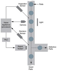
A machine vision system consists of several critical components, from the sensor (camera) that captures a picture for inspection, to the processing engine itself (vision appliance) that renders and communicates the result. For any machine vision system to work reliably and generate repeatable results, it is important to understand how these crticial components interact.
The following sections will provide you with an introduction to lighting, staging, optics and cameras, all critical components of a successful machine vision solution. Additional help on these topics is available from your distributor or integrator, from IPD, and from vendors of lighting and lenses
| Lighting | Staging | Lenses | Cameras |
 |
 |
 |
 |
Industrial applications of Machine Vision include:
The human eye can see well over a wide range of lighting conditions, but a machine vision system is not as capable. You must therefore carefully light the part being inspected so that the machine vision system can clearly 'see' them.
The light must be regulated and constant so that the light changes seen by the machine vision system are due to changes in the parts being inspected and not changes in the light source.
You will want to select lighting that 'amplifies' the elements of the part that you want to inspect and 'attenuates' elements that you don't want to inspect. In the left picture, poor lighting makes it difficult to read the letters on this part. In the right picture, the lighting has been selected to clearly show the lettering.
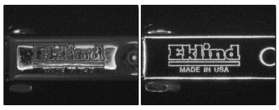
Images courtesy of NER / RVSI, Inc.
Proper lighting makes inspection faster and more accurate. Poor lighting is a major cause of failure in machine vision inspection systems.
In general, the available or ambient light is poor lighting and will not work. For example, the overhead lights in a factory can burn out, dim or be blocked, and these changes might be interpreted as part failures by the machine vision system.
Selecting the proper lighting requires some knowledge and experience. Our distributors and lighting vendors will be able to do an analysis of the parts you want to inspect and recommend proper lighting.
Teledyne DALSA works with the following lighting vendors:
| Advanced Illumination (www.advancedillumination.com) 24 Peavine Drive Rochester, VT 05767 USA 802-767-3830 x221 |
CCS America (www.ccsamerica.com) CCS America, Inc. 48 Weston St. Waltham, MA 02453 USA 781-899-2494 |
| Metaphase Technologies (www.metaphase-tech.com) 3580 Progress Drive Bensalem, PA 19020 USA 215-639-8699 |
ProPhotonix Limited (www.prophotonix.com) 32 Hampshire Road Salem, NH 03870 USA 800-472-4633 |
| Smart Vision Lights (www.smartvisionlights.com) 2359 Holton Road Muskegon, MI 49445 USA 231-722-1199 |
Back Lighting
On-Axis Lighting
Dome Lighting
Spot Lighting
Dark Field Lighting
Staging usually is mechanical. It also usually includes a Part-in-Place sensor that tells the machine vision system when a part is in front of the camera. This sensor is usually a simple light source and photoelectric detector, for example
Staging, sometimes called fixturing, holds the part to be inspected at a precise location in front of the camera for a Vision Appliance™ to 'see'. Staging is required for three reasons:
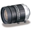
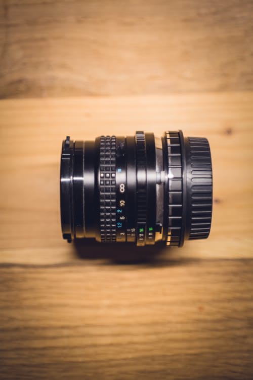
The lens gathers the light reflected (or transmitted) from the part being inspected, and forms an image in the camera sensor. The proper lens allows you to see the field-of-view you want and to place the camera at a convenient working distance from the part.
To pick the proper lens you will first need to know the field-of-view (FOV) and the working distance. The FOV is the size of the area you want to capture.
Here is a typical example: If the part to be inspected is 4" wide and 2" high, you would need a FOV that is slightly larger than 4", assuming your staging can position the part within this FOV. In specifying the FOV you have to also consider the camera's "aspect ratio" - the ratio of the width to height view. The cameras used with Vision Appliances™ have a 4:3 aspect ratio. In the previous example, the 4" x 2" part size would fit in a 4:3 aspect ratio, but a 4" x 3.5" part would require a larger FOV to be entirely seen.
The working distance is approximately the distance from the front of the camera to the part being inspected. A more exact definition takes into account the structure of the lens.
From the FOV and working distance and the camera specifications, the focal length of the lens can be estimated. The focal length is a common way to specify lenses and is, in theory, the distance behind the lens where light rays 'from infinity' (parallel light rays) are brought to a focus. Common focal lengths for lenses in machine vision are 12 mm, 16 mm, 25 mm, 35 mm and 55 mm. When the calculations are done, the estimated focal length will probably not exactly match any of these common values. We typically pick a focal length that is close and then adjust the working distance to get the desired FOV.
There are other important specifications for lenses, such as resolution (image detail - depends on the camera and the lens), the amount and type of optical distortion the lens introduces and how closely the lens can focus.
Given all of these issues, we recommend that you work closely with your DALSA IPD distributor to choose the appropriate lens for your application.

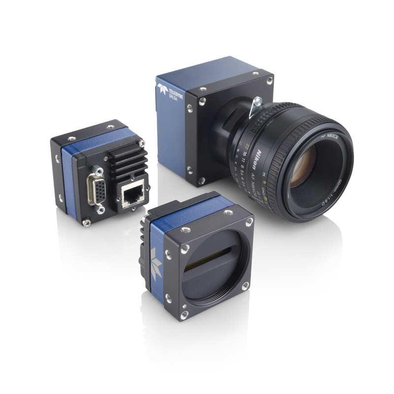
Teledyne DALSA Falcon and Genie Nano area scan cameras
Teledyne DALSA Linea line scan cameras
The camera contains a sensor that converts light from the lens into electrical signals. These signals are digitized into an array of values called pixels and processed by a Vision Appliance™ to perform the inspection.
The resolution (precision) of the inspection depends upon the working distance, the field-of-view (FOV), and the number of physical pixels in the camera's sensor. A standard VGA camera has 640 x 480 physical pixels (width x height), and each physical pixel is about 7.4 microns square. From these numbers, resolution can be estimated for your "real world" units. We usually specify resolution as a fraction of a physical pixel, as this is independent of your particular imaging set-up.
The sensors used by machine vision cameras are highly specialized, and hence more expensive than say, a web cam. First, it is desirable to have square physical pixels. This makes measurement calculations easier and more precise. Second, the cameras can be triggered by the machine vision system to take a picture based on the Part-in-Place signal. Third, the cameras have sophisticated exposure and fast electronic shutters that can 'freeze' the motion of most parts.
Teledyne DALSA offers a full range of Area Scan (2D sensors) and Line Scan (1D sensors) cameras that interface with our Vision Appliance controllers.
View Teledyne DALSA Cameras