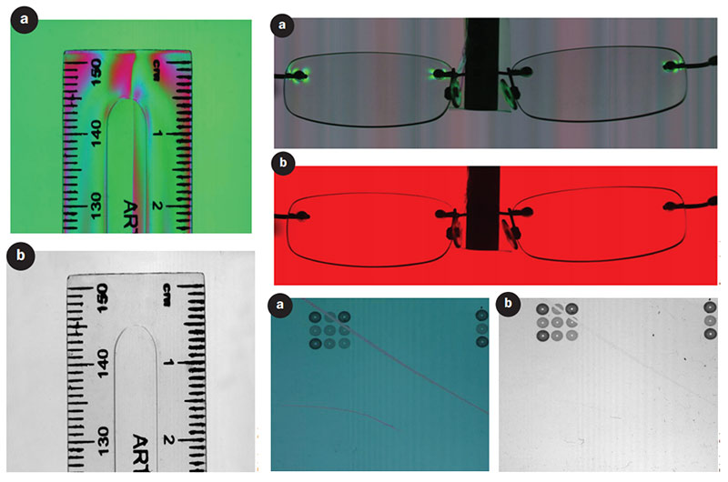
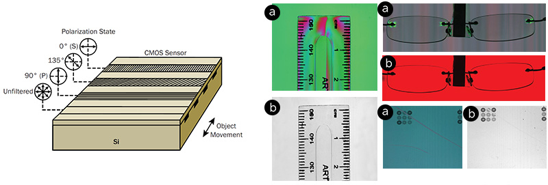
Polarization cameras detect birefringence, stress, surface roughness, and physical properties unseen by conventional imaging.
Fundamental Properties of Light:
1. Wavelength
2. Intensity
3. Polarization
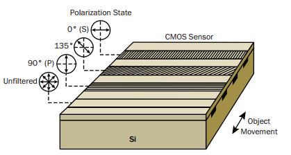
A micropolarizer array consisting of nanowires is placed on top of the silicon; the nanowires have a pitch of 140 nm and a width of 70 nm, while the orientation of the micropolarizer filters is 0°, 135° and 90°, respectively, on the first three linear arrays. The intensity of the filtered light is recorded by the underlying arrays. The fourth channel is an unfiltered array, which captures the total intensity, equivalent to a conventional image, while the gaps in between the active arrays reduce spatial crosstalk.
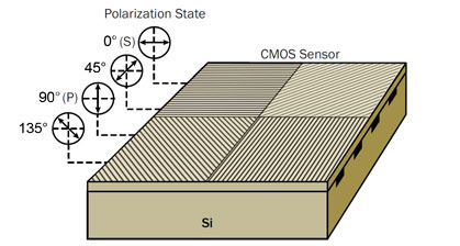
The sensor incorporates a layer of polarizers above the photodiodes. Four different angled polarizers (90°, 45°, 135° and 0°) are placed above the sensor’s pixels with every block of four pixels making up a calculation unit. From the relationship between the different directional polarizers and the resulting pixel output, standard algorithms can calculate both the degree and direction of polarization
Polarization offers numerous benefits, not only detecting geometry and surface, but measuring physical properties that are not detectable using conventional imaging. In machine vision, it can be used to detect stress, inspect objects, reduce glare from transparent objects, and enhance contrast for objects that are difficult to distinguish otherwise. When combined with phase detection, polarization imaging is much more sensitive than conventional imaging. To learn more, read "Focus on Polarization: Quadlinear Line Scan Camera Detects Multiple Polarization States" by Teledyne DALSA, published in Photonics Spectra July 2016.
 Read "Focus on Polarization: Quadlinear Line Scan Camera Detects Multiple Polarization States